Spark Gap Tesla Coil v1 - Wardcliff
Overview
This is the first spark gap coil I have designed entirely from scratch. I have several other coils that I worked on prior to this one, but this is the first project where I really decided to try and document all my progress entirely from scratch. Below I will try to provide a detailed description of the making of this coil with failures and fixes :) The coil name is an allusion to the Wardenclyffe tower (named after the property where Nikola Tesla made his famous coil), and also to a an item in a game I played far too much when I was younger. There are many issues with this coil that will be addressed in a future (fingers crossed) coil... this has been a fantastic experience overall heavily inspired by Steve Ward's work of course! Though this is not solid-state yet...


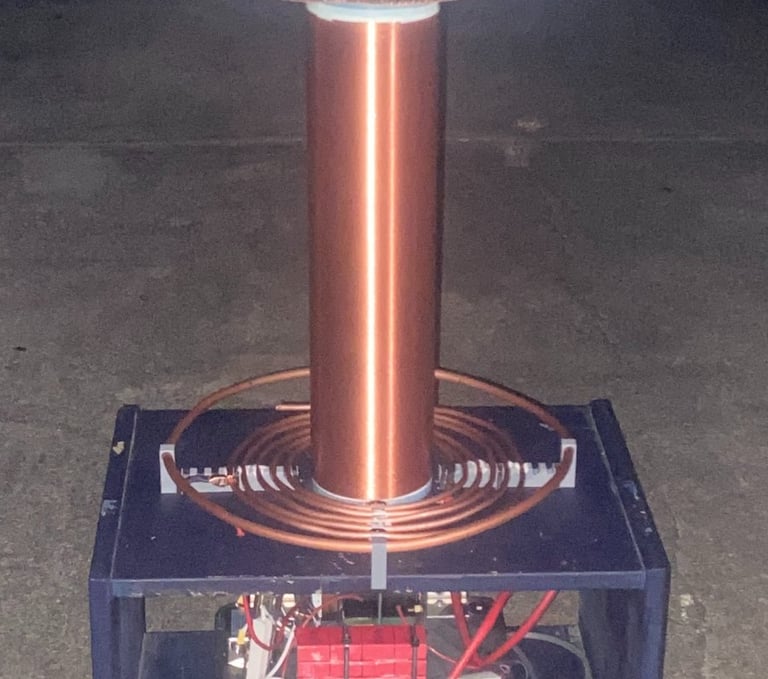
(Almost) Finalized Coil
Here is a picture of the almost finalized coil. I still have to tweak some parts of the spark gap and the the MMC ! I will list an overview of the specs involved below:
Primary coil = 4.2 uH
5 turns of 0.25" copper tubing with 0.5" spacing and 5" inner diameter
Primary Tank Capacitor (MMC) = 98.8 nF
4 strings of 4 series 0.1uF 1600vDC caps totaling 16 caps (~0.1uF 6400vDC) - Side note IK this voltage is low this will be fixed soon
Bleeder resistor(s) = 1 PCB soldered together of 40, 1/4 watt 1 Megaohm resistors (to be replaced soon also)
HV Transformer = Single Microwave Oven Transformer ~2kVAC (RMS)
To be replaced soon with a ~6kVAC (RMS) transformer
Secondary Coil resonance (w/ Toroid) = 245 kHz
~1100 turns of 0.016" enamel magnet wire with a 4.5" tubing outer diameter
Top-load = 4" Aluminum Drier duct
Spark Gap Tesla Coil Overview
Here is a schematic of a spark gap coil that I designed. I have included more than the usual schematic because I think it is important to include all of the functional components and safety features:


V1 is 120v RMS mains and S1 is a 20 amp fuse. Boxed in green is the power indicator, and boxed in red is the Electromagnetic Interference (EMI) filter. The EMI filter is not included in most schematics but is actually a pretty important component of the spark gap tesla coil to not forget! It acts as a low-pass filter to prohibit any current or voltage spikes from returning to the wall! It is crucial to include this in the wiring diagram.
T1 is the high voltage transformer! I am using a Microwave Oven Transformer (MOT) at the moment, but it is soon to be replaced with a stronger magnetic shunted transformer. The current setup barely runs at 2 kV RMS output, so I am trying to get the new transformer to have about 6 kV RMS. (Maybe even a parallel wiring of 8 kV RMS together !) The spark gap, V2, is currently a static gap but I have plans to make a rotary one in the future.
Boxed in purple, the primary tank circuit includes the Mini-Multi Capacitor (MMC) [~0.988uF and ~6.4kV] and the primary coil [~4.2uH]. When the spark gap quenches (fires) the charge stored in the primary tank circuit essentially bounces between C6 and L5 at ~245 kHz in my setup. During this time the power is transferred over several cycles of oscillation to the secondary resonant circuit in blue. There, the secondary coil (right half of L5) gains power and pushes charge into the top-load. This charge is then discharged to ground via the C7 parasitic capacitance.
Most schematics of a tesla coil shown online do not show the secondary resonant circuit (they leave the secondary output floating)! I think this is bad practice as it actually hides the functionality of the circuit behind the ambiguity of the parasitic capacitance; hence, it is shown here for completeness.
Designing, Making, and Testing the Secondary Coil
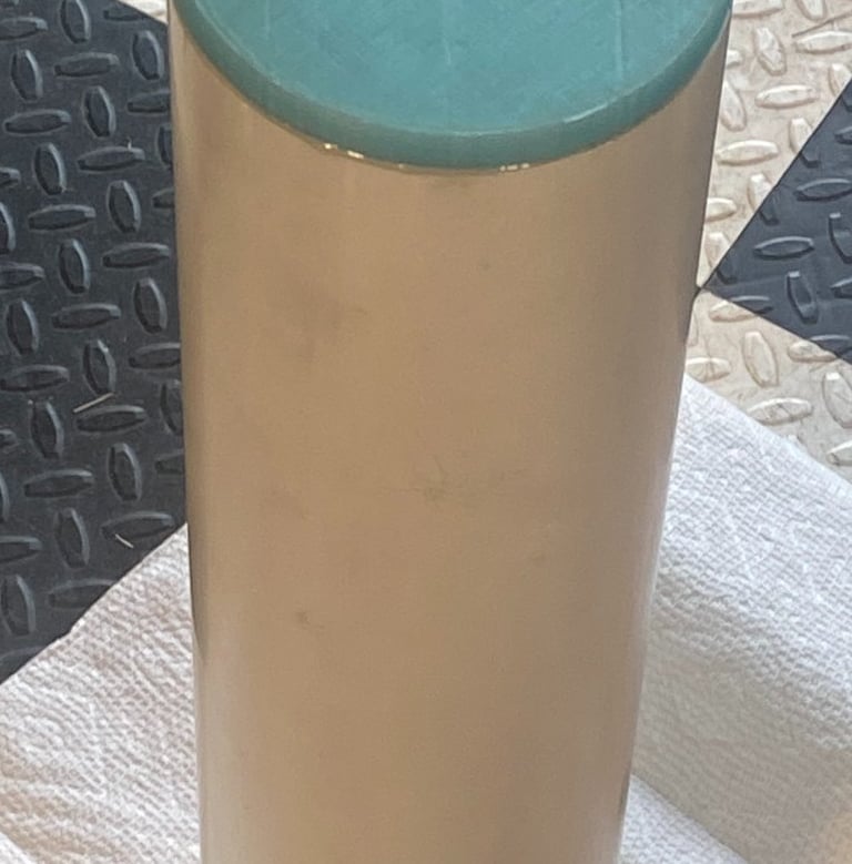
The typical ratio of height to width of a secondary coil is ~4:1, so using this metric a piece of PVC pipe was found and cleaned off. I then did some very rough math to see that using 0.016" diameter copper magnet wire, I could achieve ~1100 turns with no spacing. This was then confirmed with JAVATC (a handy tesla coil calculator not to be used too heavily). The ideal dimensions of the coil prior to winding was 4.5" outer diameter by 17.6" with 1100 turns of 0.016" diameter wire.
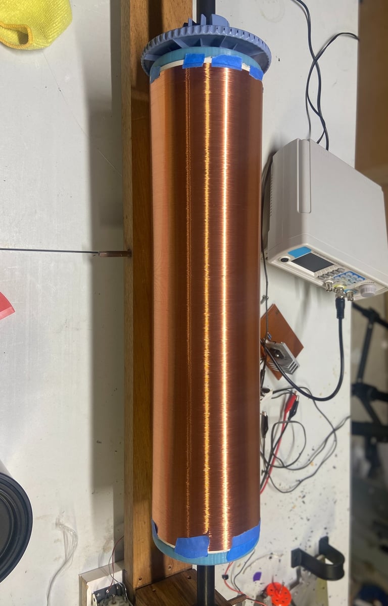
Once the wire and PVC pipe (I would use tubing in hindsight) were on hand, most of the setup time was spent creating a motor driver circuit from a signal given by a function generator and creating the physical apparatus to spin the coil on. I even 3D printed glow in the dark endcaps to see if I could capture the arc striking in the glow of the filament later! If one desired to wind the coil by hand, they would be in for a world of prolonged torture. Thus, it is almost essential to create a sort-of makeshift lathe and setup to coil to guide the wire when wrapping it around.
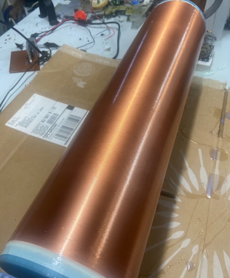
Once the coil had been wound, I covered it in 3 or 4 layers of polyurethane coating to ensure the windings would stay seated in the proper spots and that the coil had some level of protection outside of the enamel.


